 Our design
Greenhouses
Our designDesigned by DIY Outdoor Builds and checked board by board in a 3D model built from real lumber sizes. We have not built this one yet, so measure as you go.
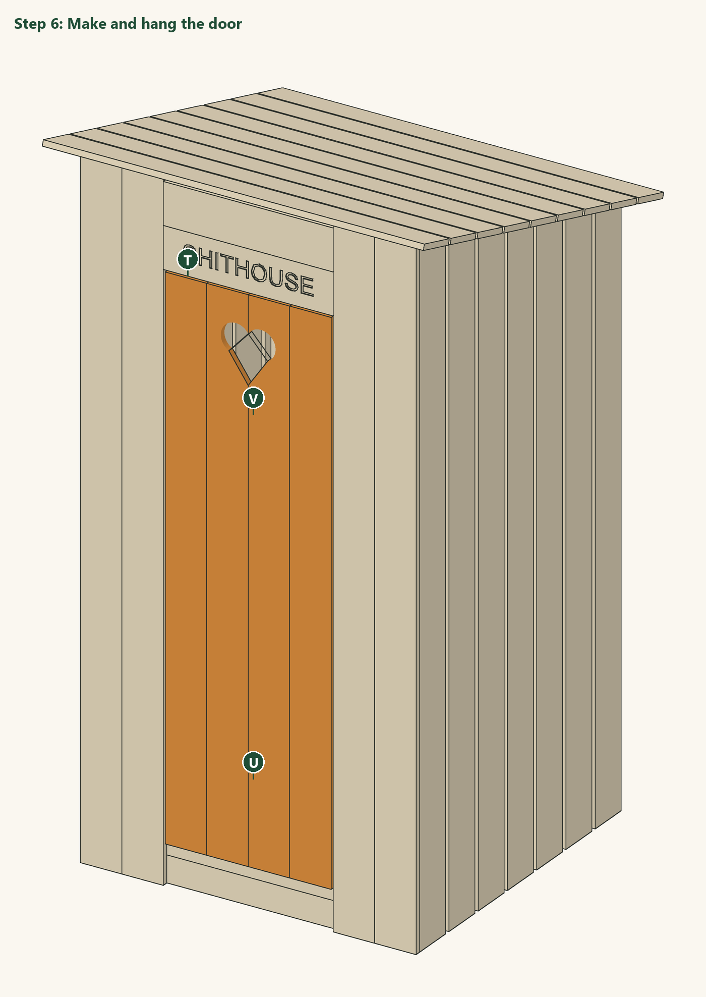
The outhouse as everyone pictures it: board siding, a roof sloping to the back, a plank door with a heart cut out, and a bench seat inside. Above the door, a routed sign gives it its name. Built from standard lumber, with every board modelled and checked in 3D.
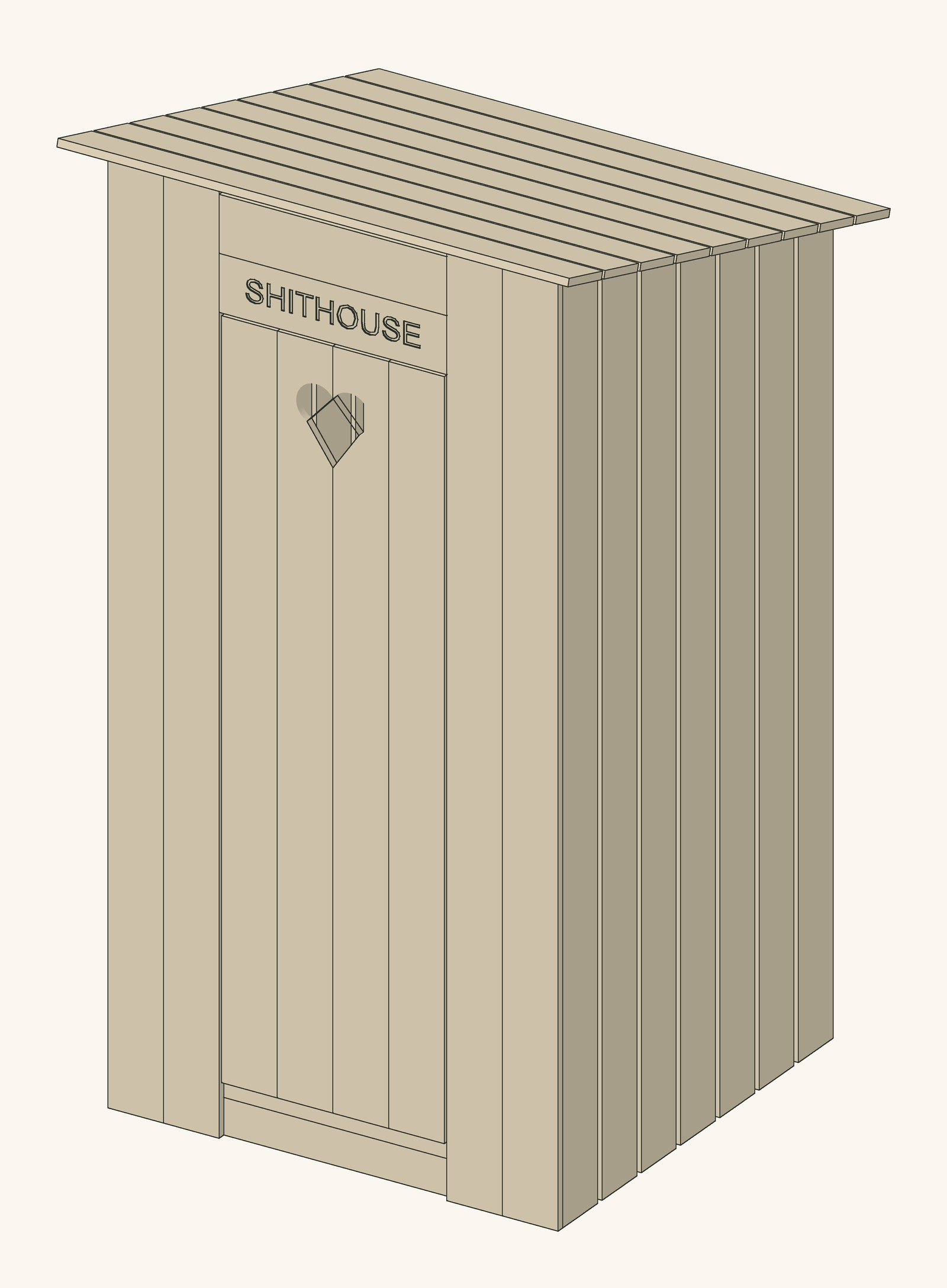
This is a classic one-seat outhouse, about 3½ ft (1.1 m) square inside the walls and 7½ ft (2.3 m) high at the front. The floor sits on a 2×4 frame so it stays off the ground. Corner posts, door studs, a header, girts and two sloping side plates make a light frame; the roof boards slope 15.9° to the back, so rain runs off behind the building and not onto the door.
The walls are vertical 1×6 boards with small gaps, which lets air through, as an outhouse needs. The side boards are cut along their tops to follow the roof, so each of the seven boards on a side has its own length, all listed in the cut list. The door is four boards held by two rails and a diagonal brace that rises from the hinge side, the classic Z, with the heart cut through the two middle boards near the top. Inside, a bench seat with a 10 in (25 cm) hole spans the back of the room.
The routed sign above the door reads SHITHOUSE, a small nod to a certain 2018 remark that left Norway, where this site is run, on the right side of the comparison. Leave the sign plain or route your own name if you prefer.
We modelled the outhouse board by board in 3D and checked that no two boards overlap and every board is fixed to another (the door through its hinges). We have not built this exact outhouse yet, so measure the real frame before cutting the siding.
| Item | Qty | Notes |
|---|---|---|
| 2×4 boards, 10 ft (3 m), pressure-treated | 8 | Floor frame, posts, studs, girts, plates, seat cleats |
| 2×6 boards, 8 ft (2.4 m), pressure-treated | 4 | Floor boards |
| 1×6 boards, 8 ft (2.4 m) | 38 | Siding, roof boards, door, seat and sign |
| 1×4 board, 8 ft (2.4 m) | 1 | Door rails and brace |
| Roofing felt and nails, or a corrugated sheet about 4 × 4½ ft (1.2 × 1.4 m) | 1 roof | The roof boards alone are not waterproof |
| T-hinges, 8 in (20 cm), with screws | 2 | On the door rails |
| Door latch or hook and eye, inside and outside | 1 set | |
| Exterior screws 3 in (76 mm) and 1⅝ in (41 mm) | About 150 + 350 | Long ones for the frame, short ones for boards |
| Solid concrete blocks | 4 | Under the corners of the floor frame |
| Part | Qty | Length | Section | Notes |
|---|---|---|---|---|
| A · Floor rim | 2 | 43 in (1092 mm) | 2×4 (1½ × 3½ in / 38 × 89 mm) | Pressure-treated or cedar |
| B · Floor joist | 3 | 39 in (991 mm) | 2×4 (1½ × 3½ in / 38 × 89 mm) | Pressure-treated or cedar |
| C · Floor board | 7 | 43 in (1092 mm) | 2×6 (1½ × 5½ in / 38 × 140 mm) | Pressure-treated or cedar |
| D · Front post | 2 | 83 in (2108 mm) | 2×4 (1½ × 3½ in / 38 × 89 mm) | Pressure-treated or cedar |
| E · Back post | 2 | 72 in (1829 mm) | 2×4 (1½ × 3½ in / 38 × 89 mm) | Pressure-treated or cedar |
| F · Back girt | 1 | 40 in (1016 mm) | 2×4 (1½ × 3½ in / 38 × 89 mm) | Pressure-treated or cedar |
| F · Side girt | 2 | 35 in (889 mm) | 2×4 (1½ × 3½ in / 38 × 89 mm) | Pressure-treated or cedar |
| G · Door jamb stud | 2 | 72 in (1829 mm) | 2×4 (1½ × 3½ in / 38 × 89 mm) | Pressure-treated or cedar |
| H · Door header | 1 | 25½ in (648 mm) | 2×4 (1½ × 3½ in / 38 × 89 mm) | Pressure-treated or cedar |
| J · Side plate | 2 | 43¾ in (1110 mm) | 2×4 (1½ × 3½ in / 38 × 89 mm) | Pressure-treated or cedar. Both ends cut plumb, 15.9° from square, parallel; length is the long edge |
| K · Seat cleat | 2 | 22 in (559 mm) | 2×4 (1½ × 3½ in / 38 × 89 mm) | Pressure-treated or cedar |
| L · Seat front board | 3 | 40 in (1016 mm) | 1×6 (¾ × 5½ in / 19 × 140 mm) | Pressure-treated or cedar |
| M · Seat board | 4 | 40 in (1016 mm) | 1×6 (¾ × 5½ in / 19 × 140 mm) | Pressure-treated or cedar. Square; the two middle boards get the 10 in (25 cm) hole |
| N · Roof board | 9 | 50½ in (1283 mm) | 1×6 (¾ × 5½ in / 19 × 140 mm) | Pressure-treated or cedar |
| P · Side siding board | 2 | 78⅜ in (1991 mm) | 1×6 (¾ × 5½ in / 19 × 140 mm) | Pressure-treated or cedar. Top cut at 15.9° to follow the roof; length is the long edge |
| P · Side siding board | 2 | 80⅛ in (2035 mm) | 1×6 (¾ × 5½ in / 19 × 140 mm) | Pressure-treated or cedar. Top cut at 15.9° to follow the roof; length is the long edge |
| P · Side siding board | 2 | 81⅞ in (2080 mm) | 1×6 (¾ × 5½ in / 19 × 140 mm) | Pressure-treated or cedar. Top cut at 15.9° to follow the roof; length is the long edge |
| P · Side siding board | 2 | 83¾ in (2126 mm) | 1×6 (¾ × 5½ in / 19 × 140 mm) | Pressure-treated or cedar. Top cut at 15.9° to follow the roof; length is the long edge |
| P · Side siding board | 2 | 85½ in (2170 mm) | 1×6 (¾ × 5½ in / 19 × 140 mm) | Pressure-treated or cedar. Top cut at 15.9° to follow the roof; length is the long edge |
| P · Side siding board | 2 | 87¼ in (2216 mm) | 1×6 (¾ × 5½ in / 19 × 140 mm) | Pressure-treated or cedar. Top cut at 15.9° to follow the roof; length is the long edge |
| P · Side siding board | 2 | 89 in (2261 mm) | 1×6 (¾ × 5½ in / 19 × 140 mm) | Pressure-treated or cedar. Top cut at 15.9° to follow the roof; length is the long edge |
| Q · Back siding board | 7 | 76¾ in (1949 mm) | 1×6 (¾ × 5½ in / 19 × 140 mm) | Pressure-treated or cedar |
| R · Front siding board | 4 | 89 in (2261 mm) | 1×6 (¾ × 5½ in / 19 × 140 mm) | Pressure-treated or cedar |
| S · Board above the sign | 1 | 22½ in (572 mm) | 1×6 (¾ × 5½ in / 19 × 140 mm) | Pressure-treated or cedar |
| S · Sign board | 1 | 22½ in (572 mm) | 1×6 (¾ × 5½ in / 19 × 140 mm) | Pressure-treated or cedar. Square; letters routed ⅛ in deep |
| T · Door board | 2 | 71½ in (1816 mm) | 1×6 (¾ × 5½ in / 19 × 140 mm) | Pressure-treated or cedar |
| T · Door board | 2 | 71½ in (1816 mm) | 1×6 (¾ × 5½ in / 19 × 140 mm) | Pressure-treated or cedar. Square; the two middle boards share the heart |
| U · Door rail | 2 | 20 in (508 mm) | 1×4 (¾ × 3½ in / 19 × 89 mm) | Pressure-treated or cedar |
| V · Door brace | 1 | 48¼ in (1224 mm) | 1×4 (¾ × 3½ in / 19 × 89 mm) | Pressure-treated or cedar. Both ends cut level at 19.1° from square, parallel; length is the long edge |
The cut list comes straight from the 3D model, which is checked so that no two boards overlap, every board is joined to another and every board is exactly the length listed. Measure the real gaps before cutting the parts that fit between others.
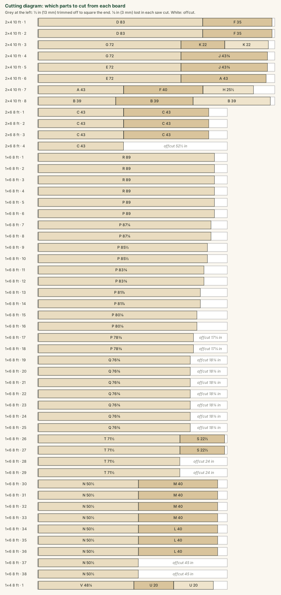
Cut the square parts from the cutting diagram first. Cut the two side plates (J) with both ends plumb at 15.9° from square, 43 11⁄16 in (1.11 m) along the long edge. Leave the side siding (P) until the frame stands, so you can check each length against it. Mark every part with its letter.
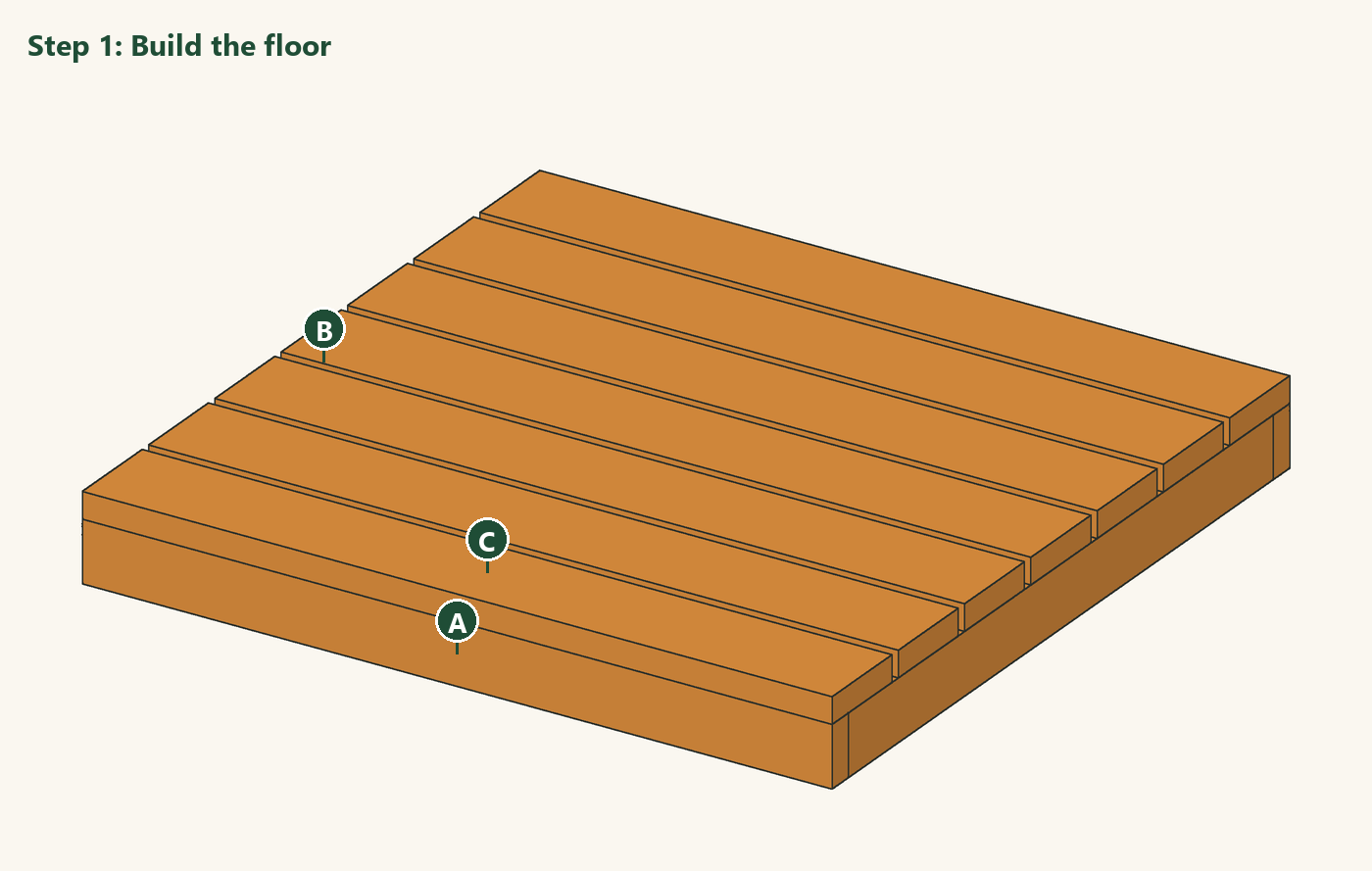
Level four concrete blocks for the corners. Build the floor frame from the two rims (A) and three joists (B), on edge, square it by measuring the diagonals, and set it on the blocks. Screw the seven floor boards (C) across the joists with small gaps for drainage.
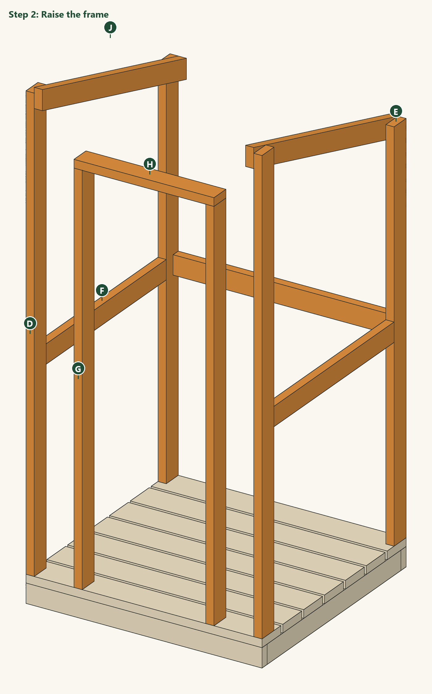
Stand the two front posts (D) and the two back posts (E) at the corners and screw them through the floor boards into the frame. Fit the door studs (G) 22½ in (57 cm) apart, inside face to inside face, and the header (H) on top of them. Screw the side and back girts (F) between the posts at 40 in (1 m). Screw the sloping side plates (J) to the inside faces of the posts, 1 in above the front post tops and level with the back post tops, so they follow the roof line.
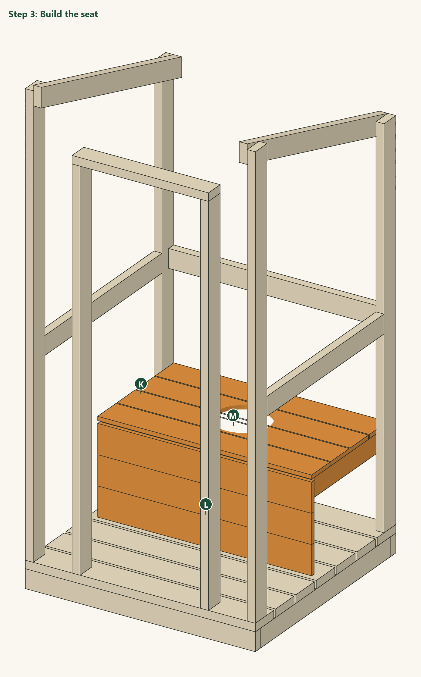
Screw a seat cleat (K) along each side wall at the back, top 17 in (43 cm) above the floor. Screw the three seat front boards (L) across the front ends of the cleats, then the four seat boards (M) on top. Cut the 10 in (25 cm) hole through the two middle seat boards with a jigsaw and sand its edge smooth.
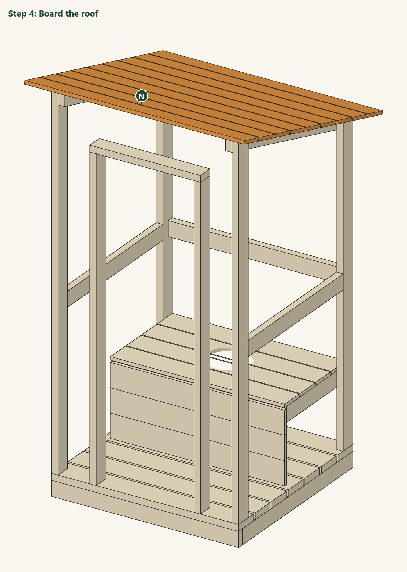
Screw the nine roof boards (N) across the side plates, starting at the front about 3 in (8 cm) past the front wall, with the same overhang at both sides. Cover the boards with roofing felt or a sheet before any rain, lapping each layer over the one below it.
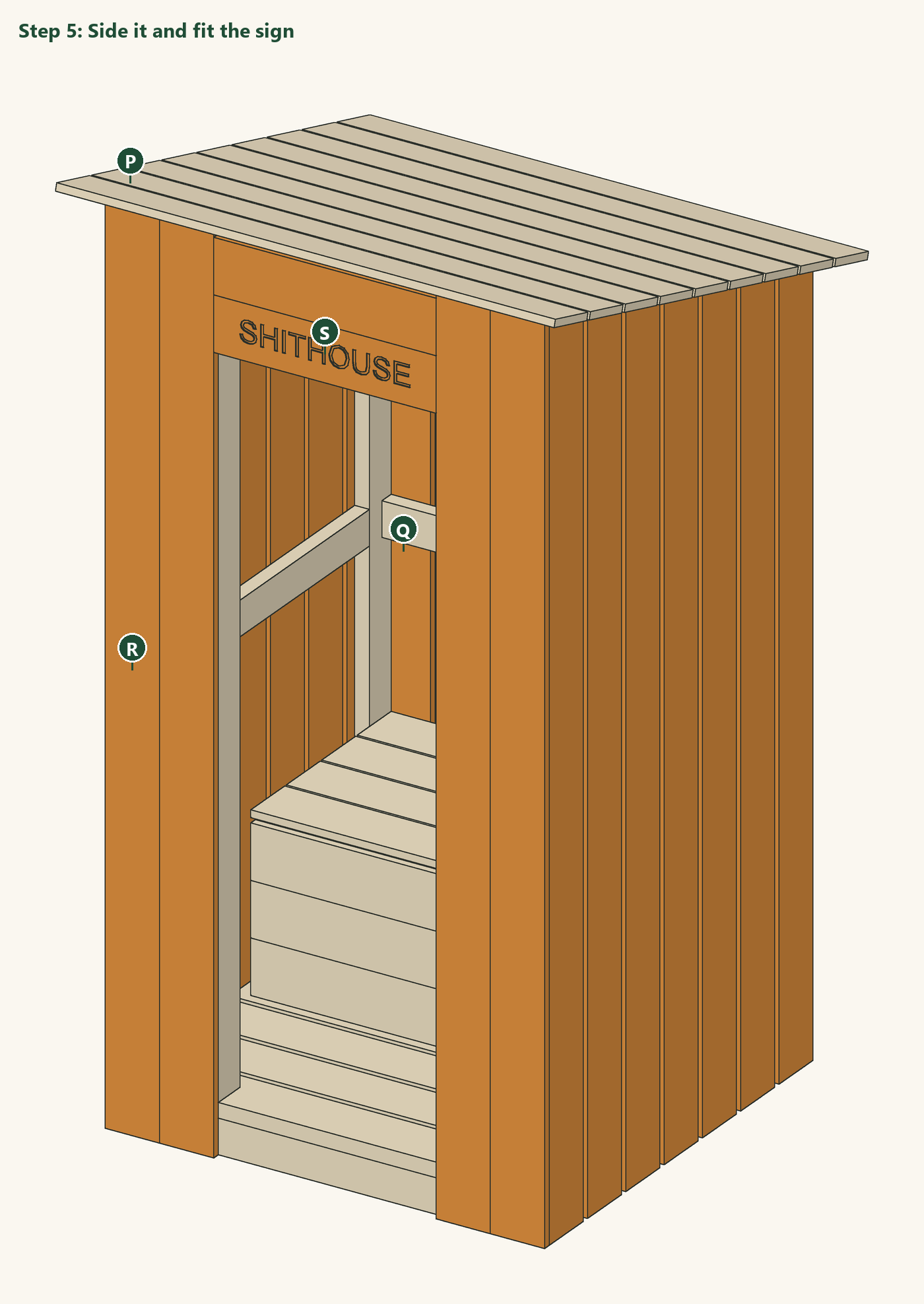
Fix the back siding (Q) with ¾ in (19 mm) gaps. Hold each side board (P) in place, mark the roof slope across its top with the bevel gauge, cut it at 15.9° and fix it, longest at the front. Fit the four front boards (R) beside the door opening. Route SHITHOUSE (or your own name) ⅛ in deep into the sign board (S) before you fix it above the door, then fit the plain board above it.
Lay the four door boards (T) face down, screw the two rails (U) across them and fit the diagonal brace (V) between the rails, rising from the hinge side. Draw the heart across the joint between the two middle boards near the top, drill a hole inside the outline and cut it with a jigsaw. Hang the door on two T-hinges screwed into the rails, with ¼ in (6 mm) clearance all round, and fit the latch.
The 3D model and drawings of this design, free to download for your own build. Open STEP in Fusion 360, FreeCAD or most CAD programs; STL and OBJ in SketchUp (with an importer), Blender or a 3D viewer; DXF in any 2D CAD program. Units are inches.
About this design: designed and modelled by DIY Outdoor Builds; the text was drafted with AI assistance and checked against the model (see our editorial policy). Design, drawings and 3D files © DIY Outdoor Builds: free to download and build for your own use, please do not republish the files. We have not built this exact design yet.
Building work can be dangerous and may need a permit. Check local rules and use a qualified professional for electrical, gas and structural work.
Share your own version with your photos, measurements and what you changed.
Our designGreenhouses
 Real build
Greenhouses
 Real build
Outdoor Structures
 Real build
Pergolas & Gazebos
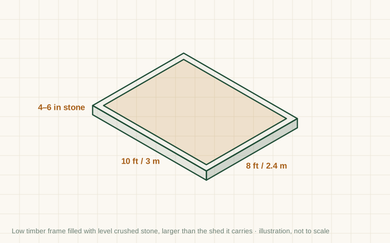 Build a Gravel Shed Base Inside a Timber FrameGarden Sheds · Intermediate · A weekend
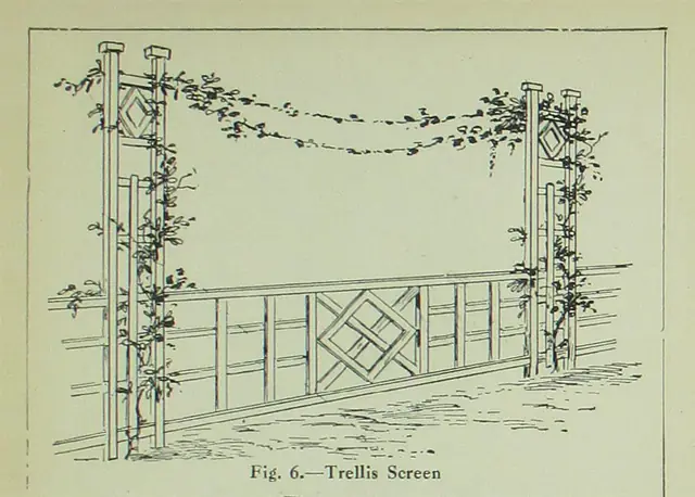 Build a Trellis Privacy Screen for a Patio or GardenPergolas & Gazebos · Intermediate · A weekend
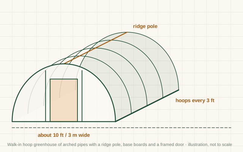 Build a Walk-In PVC Hoop GreenhouseGreenhouses · Intermediate · A weekend
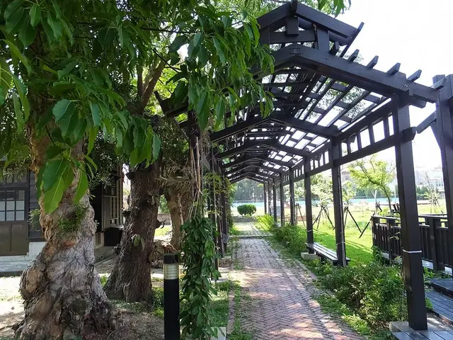 Freestanding Wooden Pergola: How to Plan and Build OnePergolas & Gazebos · Advanced · Several weekends
From diyoutdoorbuilds.com/builds/classic-outhouse-heart-door · DIY Outdoor Builds