 Our design
Outdoor Furniture
Our designDesigned by DIY Outdoor Builds and checked board by board in a 3D model built from real lumber sizes. We have not built this one yet, so measure as you go.
The picnic table everyone knows: a five-board top, a seat on each side and angled legs that cross the seat supports. Seats six adults. The leg and brace angles, the cut list and the cutting diagram all come from a checked 3D model.
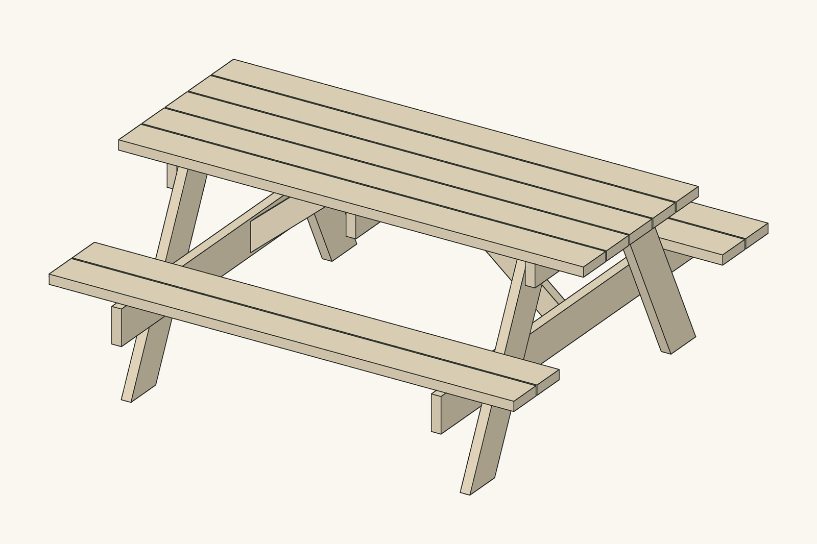
This is the classic one-piece picnic table: a 72 in (1.83 m) top 28½ in (72 cm) wide, two seats outside the legs, and A-frame legs that lean out 26.6° from vertical, which is a slope of one inch out for every two inches down. That angle puts the feet under the seats, so the table cannot tip when someone sits on the very end of a seat.
Each end is one rigid frame: a top cleat, two legs and a seat support, bolted together with carriage bolts. Two braces run from the seat supports up under the middle of the top and stop the frames from leaning, and a centre cleat ties the top boards together halfway along. Top and seats are 2×6s; the cleats and braces are 2×4s.
The angles are what make picnic tables tricky, so they are given exactly: the legs are cut level at 26.6° from square at both ends, parallel, and each brace has a plumb cut at 40° at the bottom and a level cut at 50° at the top. We modelled the table board by board and checked that no two boards overlap and that every board is fixed to another. We have not built this exact table yet, so mark the leg angles from a real leg held in place before you cut all four.
| Item | Qty | Notes |
|---|---|---|
| 2×6 boards, 8 ft (2.4 m), pressure-treated or cedar | 13 | Top, seats, legs and seat supports |
| 2×4 boards, 8 ft (2.4 m), pressure-treated or cedar | 2 | Cleats and braces |
| Carriage bolts ⅜ × 4 in (M10 × 100 mm) with washers and nuts | 8 | Two through each leg: one at the top cleat, one at the seat support |
| Exterior screws 3 in (76 mm) | About 60 | Top and seat boards, braces |
| Part | Qty | Length | Section | Notes |
|---|---|---|---|---|
| A · Top board | 5 | 72 in (1829 mm) | 2×6 (1½ × 5½ in / 38 × 140 mm) | Pressure-treated or cedar |
| B · Seat board | 4 | 72 in (1829 mm) | 2×6 (1½ × 5½ in / 38 × 140 mm) | Pressure-treated or cedar |
| C · Top cleat | 2 | 28½ in (724 mm) | 2×4 (1½ × 3½ in / 38 × 89 mm) | Pressure-treated or cedar |
| D · Leg | 4 | 31⅞ in (810 mm) | 2×6 (1½ × 5½ in / 38 × 140 mm) | Pressure-treated or cedar. Both ends cut level at 26.6° from square, parallel; length is the long edge |
| E · Seat support | 2 | 65½ in (1664 mm) | 2×6 (1½ × 5½ in / 38 × 140 mm) | Pressure-treated or cedar |
| F · Brace | 2 | 27¼ in (692 mm) | 2×4 (1½ × 3½ in / 38 × 89 mm) | Pressure-treated or cedar. Bottom cut plumb (40° from square), top cut level (50° from square); length is the long edge |
| G · Centre cleat | 1 | 28½ in (724 mm) | 2×4 (1½ × 3½ in / 38 × 89 mm) | Pressure-treated or cedar |
The cut list comes straight from the 3D model, which is checked so that no two boards overlap, every board is joined to another and every board is exactly the length listed. Measure the real gaps before cutting the parts that fit between others.
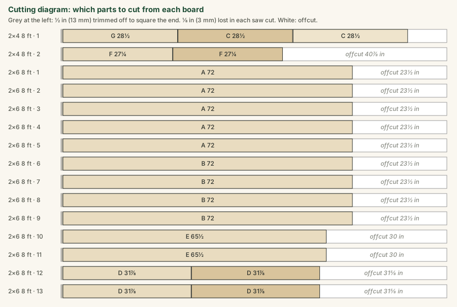
Cut the straight parts first: five top boards and four seat boards at 72 in, two seat supports at 65½ in, three 2×4 cleats at 28½ in. Then set the saw to 26.6° and cut the four legs (D) with both ends parallel, 31⅞ in (810 mm) along the long edge. Cut the two braces (F): one end plumb at 40°, the other level at 50°, 27¼ in (692 mm) along the long edge. Mark every part with its letter.
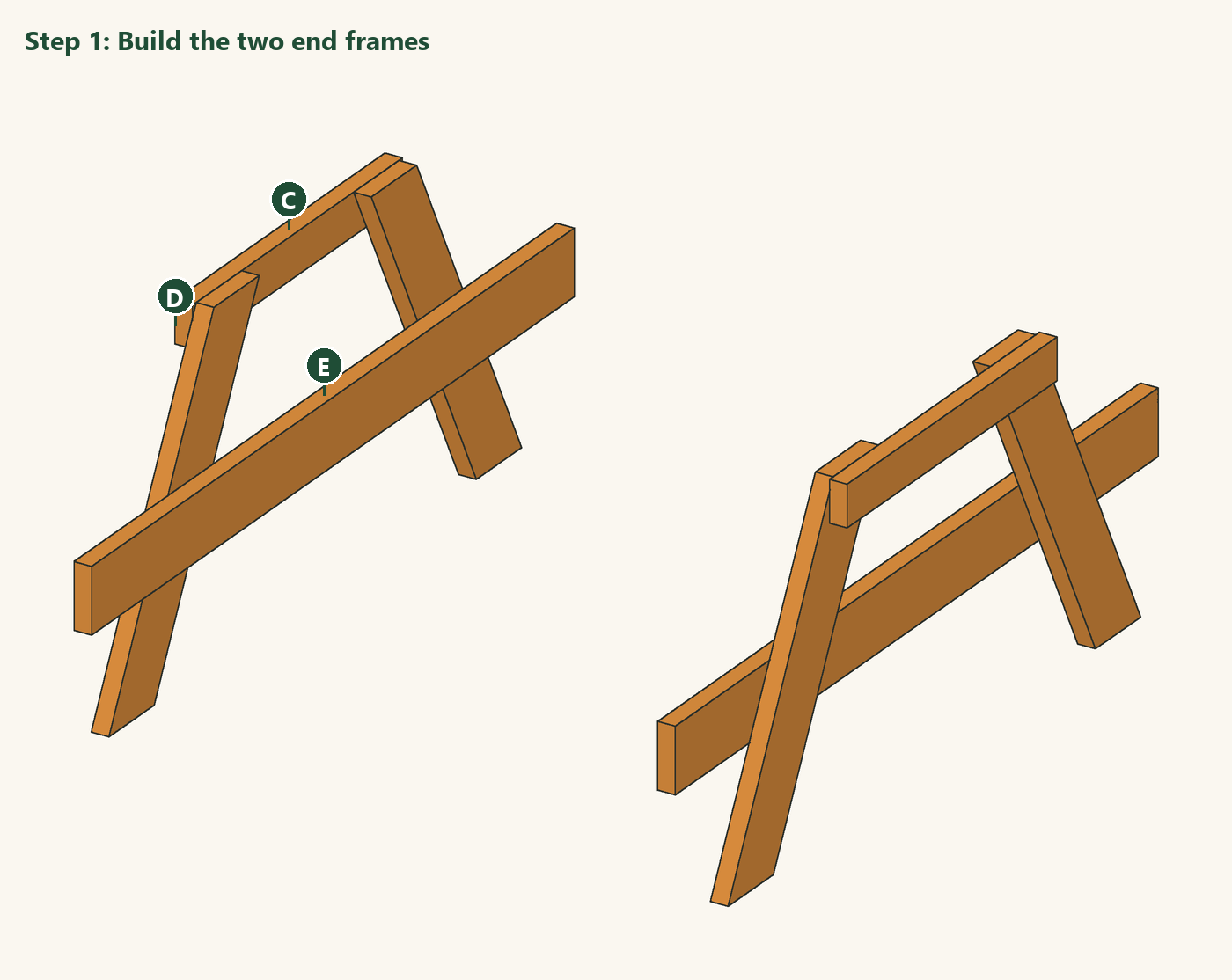
Lay a top cleat (C) and a seat support (E) on a flat floor, 12½ in (32 cm) apart, top edge of the cleat to top edge of the support. Lay two legs (D) across them so their tops are flush with the top of the cleat and they lean out evenly to both sides, and check that the frame is symmetric by measuring from each foot to the centre of the cleat. Drill through leg and cleat, and leg and support, and fit the carriage bolts. Build the second frame as a mirror image.
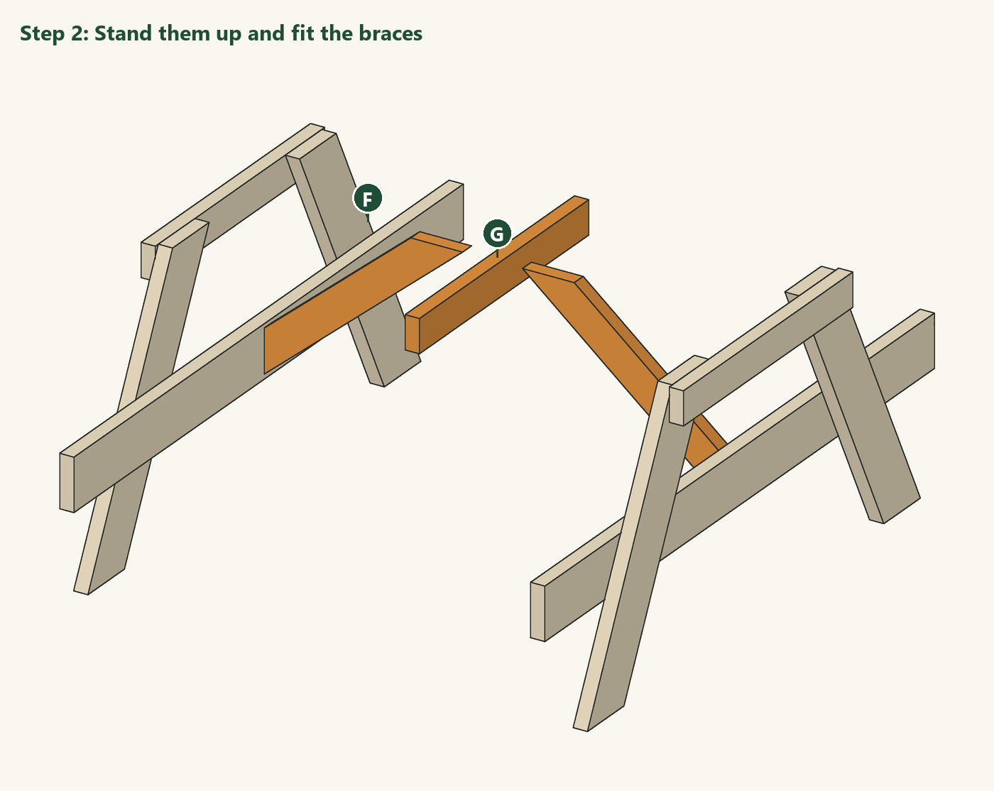
Stand both frames up 57 in (1.45 m) apart, outside face to outside face of the cleats, so the top overhangs each frame by 7½ in (19 cm), with the seat supports facing each other. Screw the centre cleat (G) under where the middle of the top will be, temporarily held by a clamp on a scrap board. Fit each brace (F) with its plumb end against the inside of a seat support at the centre of the table and its level end up under the top line, and screw it to the support.
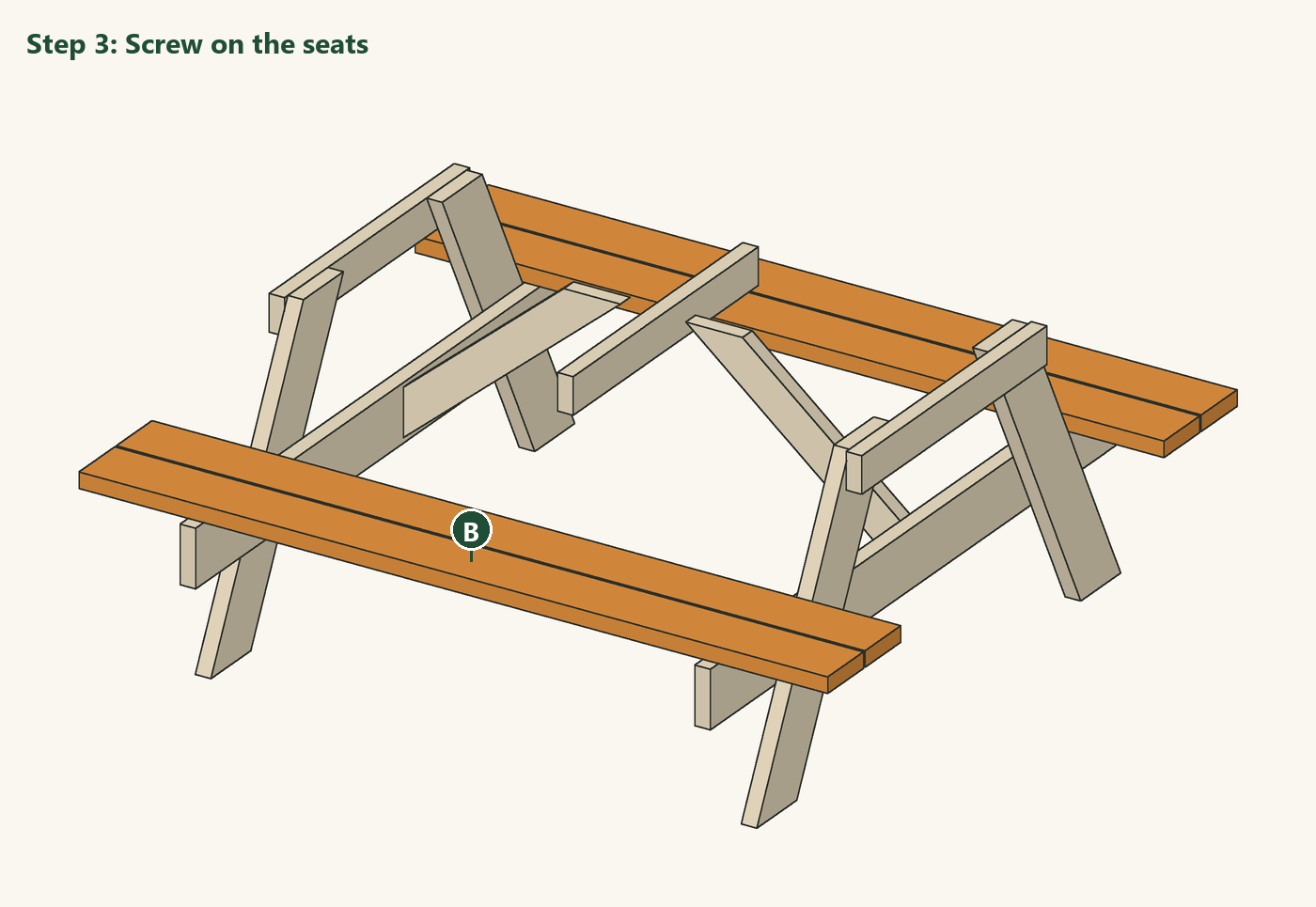
Lay two seat boards (B) on each side across the seat supports, ¼ in (6 mm) apart, with the inner board ¼ in clear of the legs and the ends overhanging the supports equally. Screw each board to both supports with two screws.
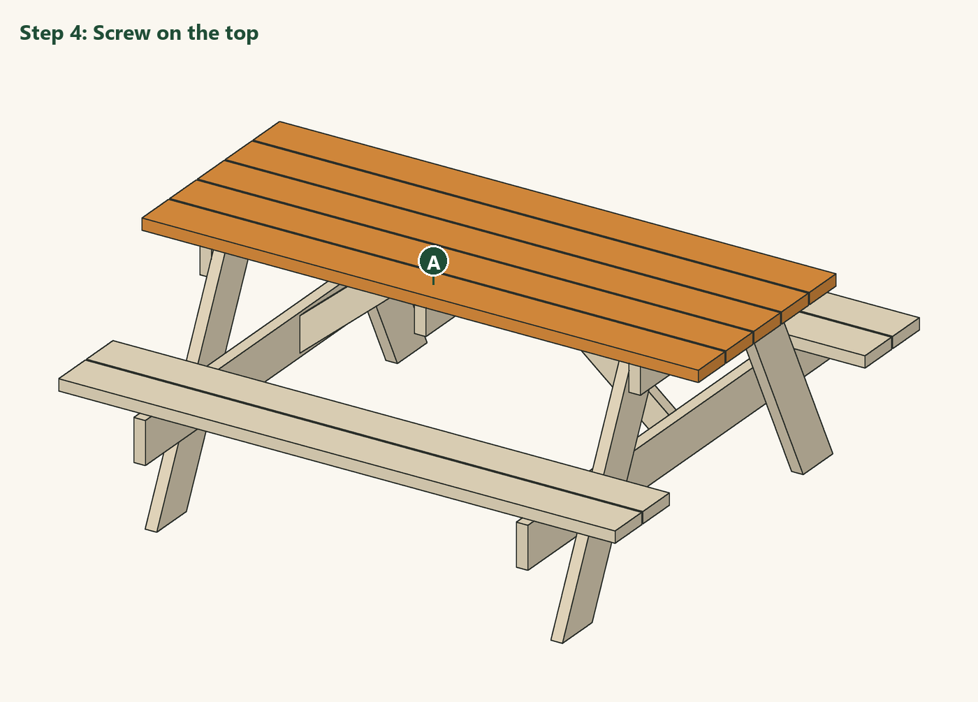
Lay the five top boards (A) on the cleats with ¼ in (6 mm) gaps, the outer boards flush with the ends of the cleats and the board ends overhanging the end frames equally. Screw each board to the three cleats and into the tops of the braces with two screws at each crossing.
Sand the top and seats, round over every edge and corner, and oil or stain the table on a dry day. Check that the bolts are tight once the wood has dried for a few weeks.
The 3D model and drawings of this design, free to download for your own build. Open STEP in Fusion 360, FreeCAD or most CAD programs; STL and OBJ in SketchUp (with an importer), Blender or a 3D viewer; DXF in any 2D CAD program. Units are inches.
About this design: designed and modelled by DIY Outdoor Builds; the text was drafted with AI assistance and checked against the model (see our editorial policy). Design, drawings and 3D files © DIY Outdoor Builds: free to download and build for your own use, please do not republish the files. We have not built this exact design yet.
Building work can be dangerous and may need a permit. Check local rules and use a qualified professional for electrical, gas and structural work.
Share your own version with your photos, measurements and what you changed.
Our designOutdoor Furniture
 Our design
Outdoor Furniture
 Our design
Outdoor Furniture
 Our design
Outdoor Furniture
 2×4 Garden Bench Plans: a Simple Backless Bench with Cut ListOutdoor Furniture · Beginner · A few hours
 Build an Entryway Shoe Storage BenchIndoor Furniture · Intermediate · About a day
 How to Hang Sturdy Wooden Wall Shelves on BracketsIndoor Furniture · Beginner · A few hours
 Potting Bench Plans: Build a Potting Bench with a Lower ShelfOutdoor Furniture · Intermediate · About a day
From diyoutdoorbuilds.com/builds/classic-picnic-table-6-ft · DIY Outdoor Builds